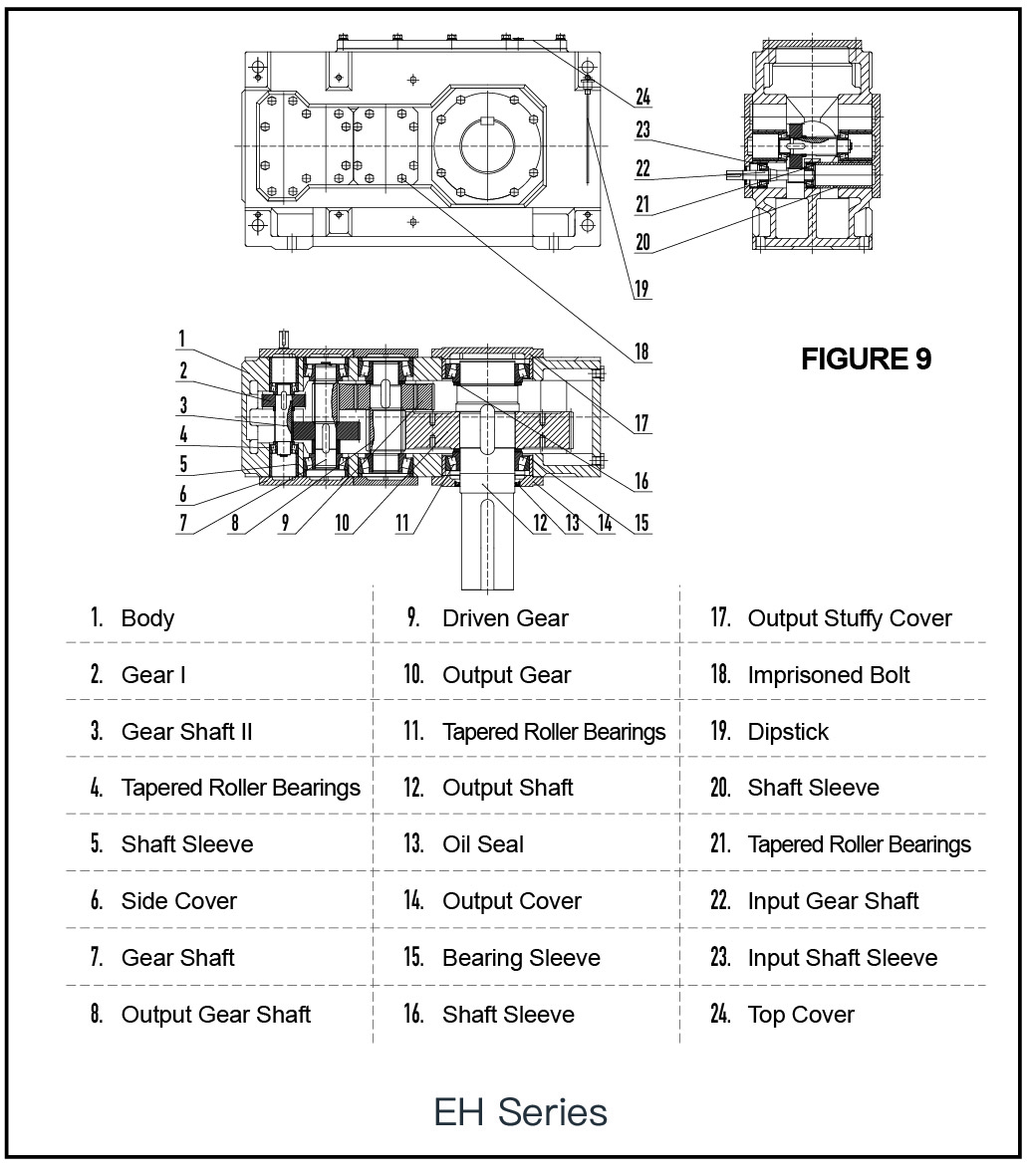
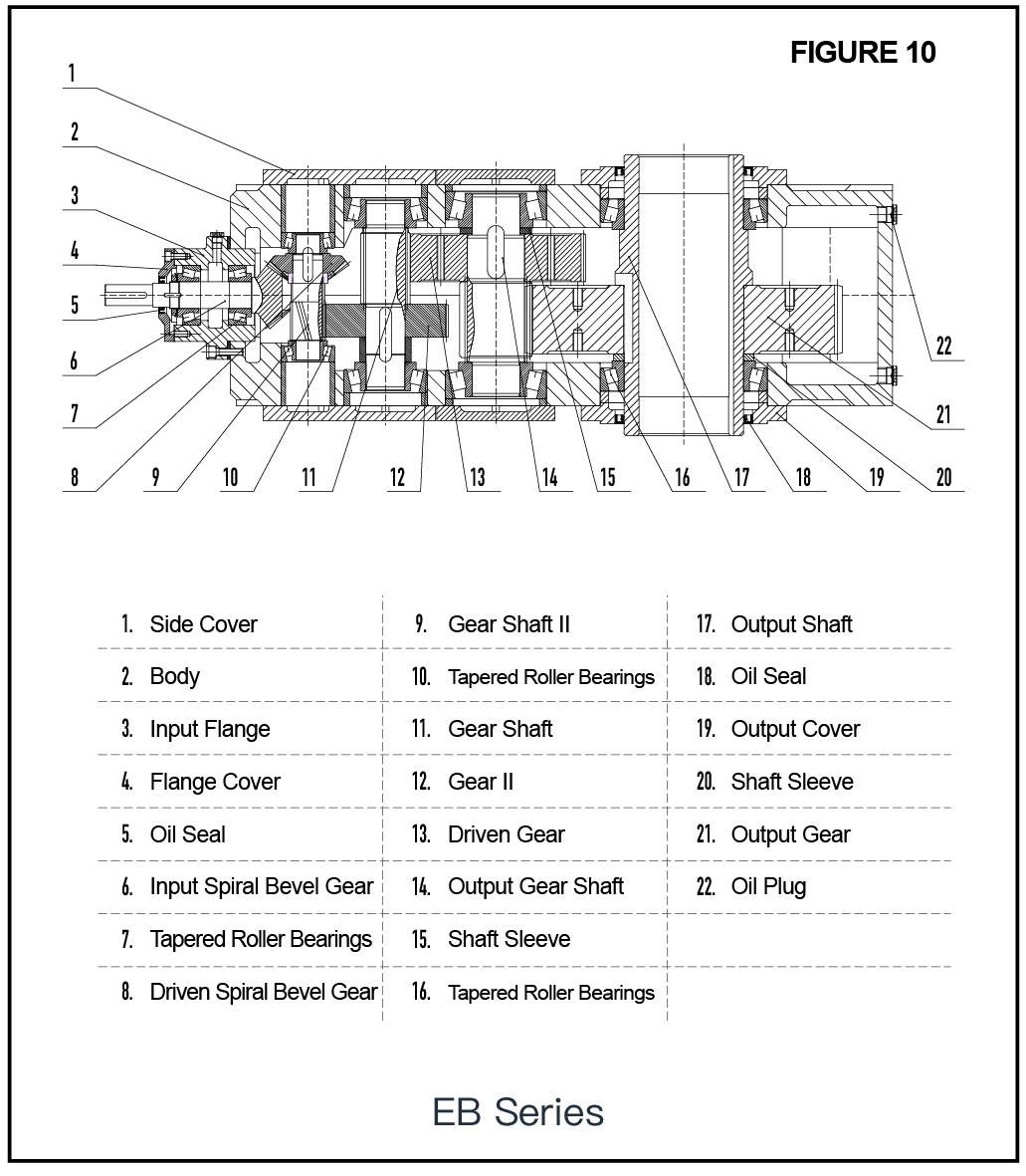
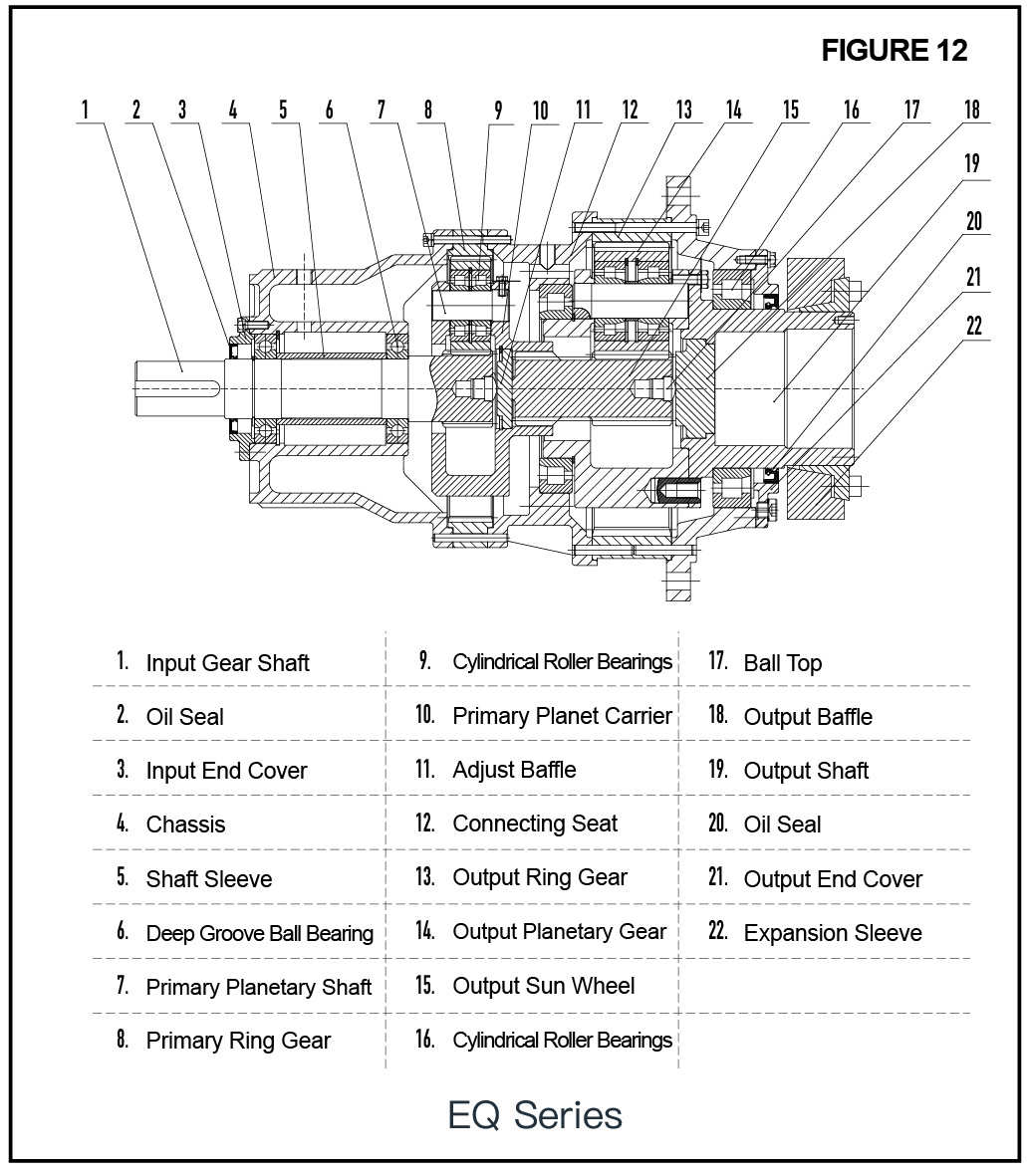
The reducer is driven by helical gears of first to fourth or more stages. This reducer can be used in various installation forms when considering the oil level.
The reducer body is made by high-strength gray cast iron. Processed by high-precision numerical control equipment, it has high matching accuracy. It avoids the overload of the gear, and its high precision also ensures the uniform load state of the bearing and the lowest noise.
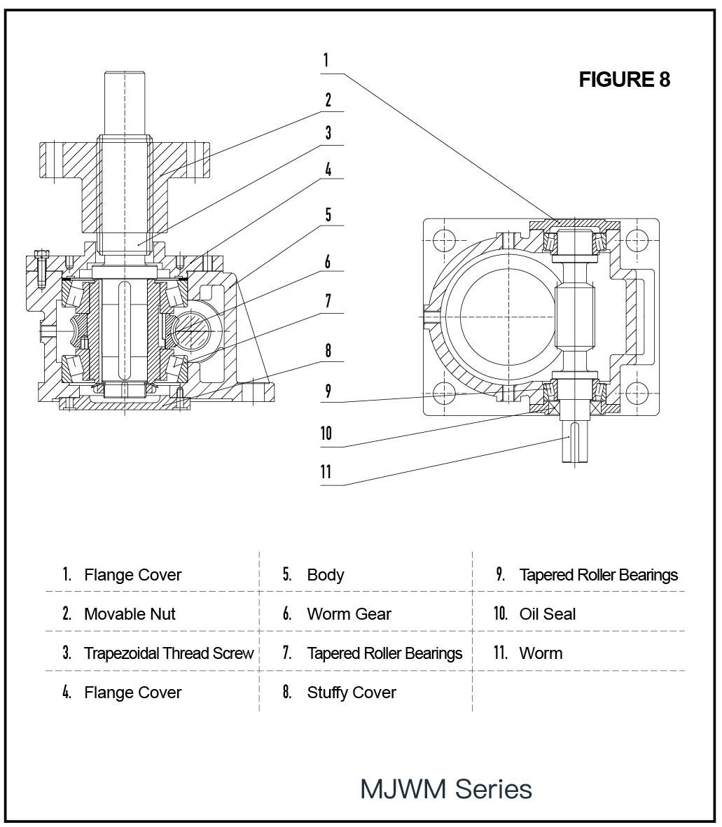
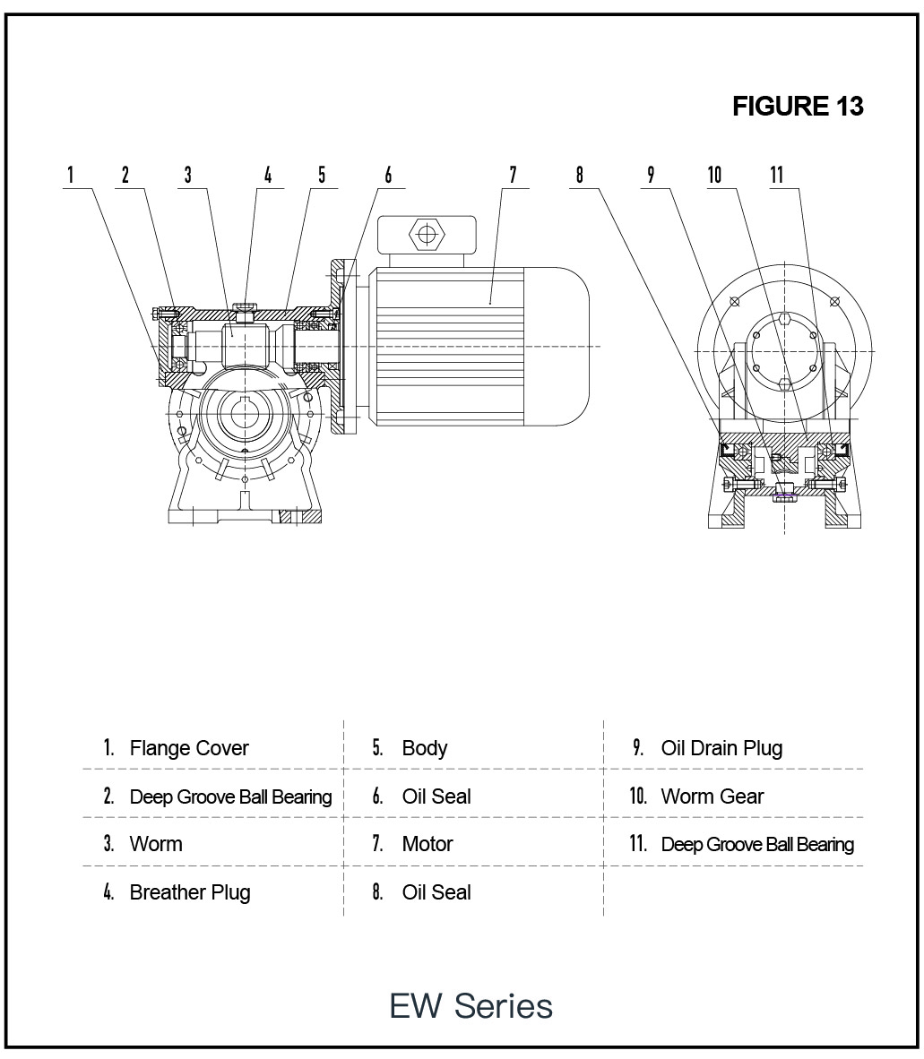
The gears are processed by heat treatment and gear grinding. The high-precision gears ensure the side clearance of the gears and make the load-bearing capacity of the tooth flank side reasonable and uniform; The worm in worm gear transmission is also treated by heat treatment and fine grinded, and the worm gear material is made of high strength wear-resistant bronze KK alloy.
Gear parts in the reducer are lubricated by oil immersion or forced lubrication. The lubricating oil is mineral oil or synthetic oil (or special oil) to ensure that gear parts will not malfunction due to poor lubrication. Generally, the increase of lubricating oil number will have an impact on the performance of the reducer. Unfavorable factors: ① Increase in oil temperature, ② Decrease in efficiency; Favorable factors: ① Reduced noise, ② Strong sealing performance, ③ Increased load-bearing capacity of worm gears or gears.
The oil seal at the output shaft prevents lubricating oil from leaking, and also prevents external dust from entering the reducer. When it is used in high ambient temperatures (heating furnaces, smelting production lines, etc.), the oil seal should be made of high-temperature resistant fluororubber materials.
The bearings used in the reducer are all wear-resistant bearings. Under the action of gears, it is oil-immersion lubrication or forced circulation lubrication. If the above two lubrication methods still cannot be used, the bearing shall be coated with sufficient grease and sealed.
The reducer generally does not require any additional cooling. The surface of the general body is sufficient to enusure the heat generated by the reducer when the reducer is running under the condition of natural air convection. [Except for
The surface paint of the reducer shall be supplied according to the default color (blue) and type when the user has no special requirements.
Check whether the description on the nameplate of the reducer or motor isconsistent with the power supply;
Check whether the reducer is in good condition(not damaged during transportation or storage);
Use standard solvent to remove the preservative on the surface of the outputshaft and the output flange;
Note! Solvents must not enter the oil seal (solvent will destroy the oil seal material)Prepare the necessary tools and auxiliary equipment:
A set of wrenches;
Torque wrench
Assembly fixture
Heating appliance
Fixing equipment, hexagonal bolts, spring washers, etc.; input/output
Original adjustment components, gaskets, bushings, etc.
Installation of solid input shaft and solid output shaft components.
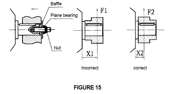
As shown in Figure 15, assembly fixtures are usually used to install parts such as driving wheels, sprockets, large gears, couplings, and pulleys on the input shaft or output shaft, and use the threaded center hole of the shaft end to connect with screws (or use heating ) Then press in.
It is not allowed to use a hammer to install parts on the input shaft or output shaft (belt pulleys, couplings, gears, etc.) by striking, as this will cause damage to the bearing, body or shaft. When installing a sprocket or gear on the input shaft or output shaft, the correct installation method can reduce the load on the shaft extension and bearing (Figure 15).
①The solid shaft contact surface must be evenly coated with lubricant.
② Auxiliary components for assembling transmission parts are not used as accessories for the reducer supply.
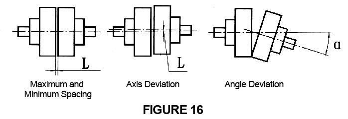
When the output shaft of the reducer and the input shaft of the working machine are connected by a coupling, the coaxiality error of the axis must not be greater than the allowable value of the
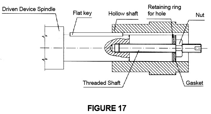
As shown in Figure 17, the working shaft is mounted on the reducer by rotating the nut, using a nut, a threaded shaft, a locking piece and a washer.
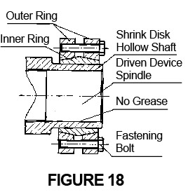
Remove the gasket between the outer ring (if installed);
Carefully remove the grease from the outer diameter of the main shaft of the driven device and the inner hole of the hollow shaft of the reducer;
Insert the main shaft of the driven device into the hollow shaft of the reducer;
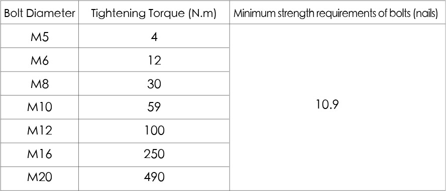
According to the tightening torque provided in Table 1, Tighten the locking screws on the shrink disk evenly one by one in a clockwise direction (not across from opposite sides). Repeat this process several times until all the locking screws reach the tightening torque.
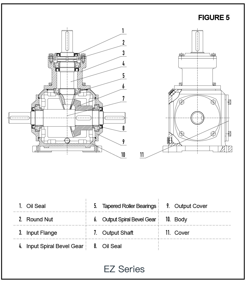
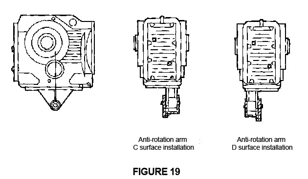
The anti-rotation arm installation of EKAT series spiral bevel gear reducer is shown in Figure 19.
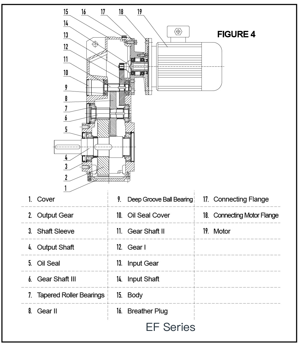
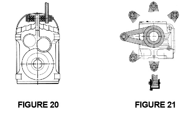
The anti-rotation arm installation of EFA series parallel shaft helical gear reducer is shown in Figure 20.
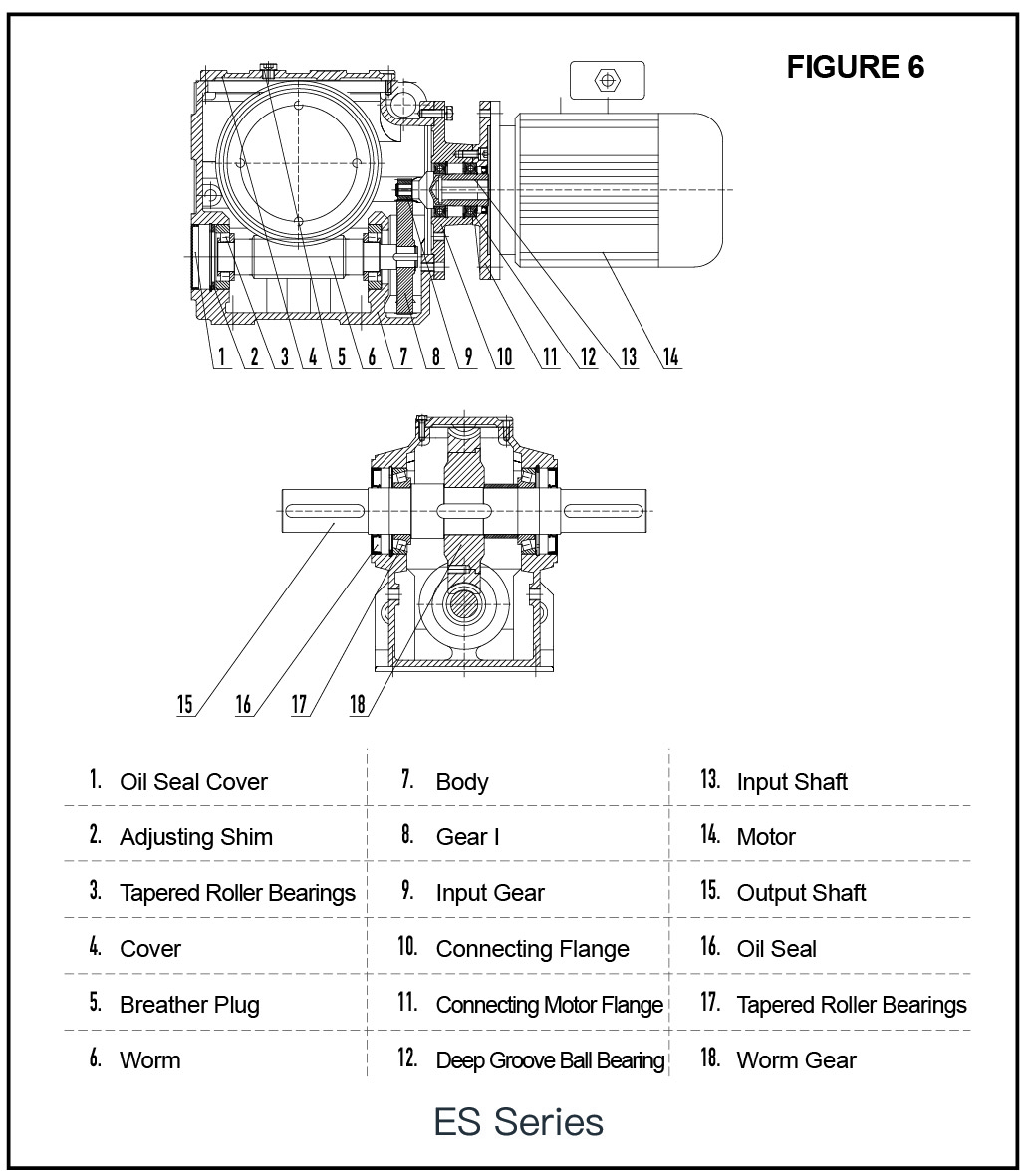
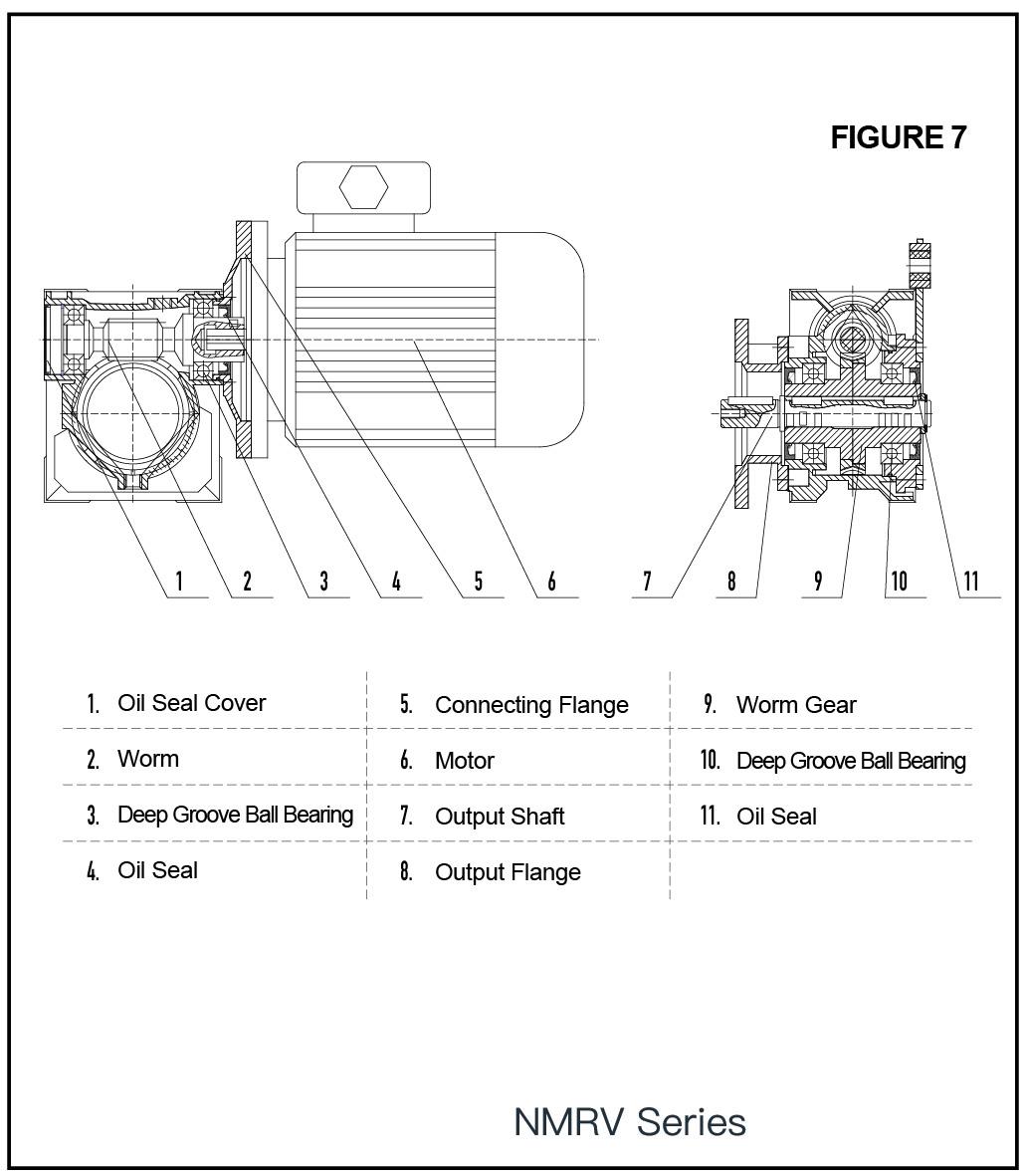
Installation of anti-rotation arm for ESAT series cylindrical worm reducer and NMRV worm gear reducer are shown in Figure 21.
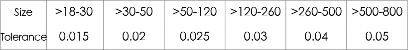
For the over-positioned connection structure, in order to ensure that no axial or radial distortion is produced, which may cause damage to the bearing and other parts, the radial runout and end runout of the over-positioned structure must meet the requirements of the following table.
Rotating parts, such as couplings, gears or pulley drives, etc., must be equipped with safety protection devices.
If any abnormality of the reducer is detected during the operation, the operation should be stopped immediately and checked and handled by professionals.
Lubricant inspection
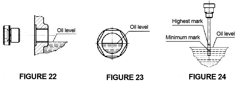
Check the oil level of the reducer
a. The oil level hole is a screw plug. Please unscrew the screw plug. If the oil level is correct, a small amount of oil will flow out of the hole. The position of the oil should at least reach the lower edge of the hole (Figure 22).
b. The oil level hole is an oil lens, and the oil position must be visible in the middle of the oil lens (Figure 23).
c. The oil level hole is a dipstick, and the oil position must be between the highest mark and the lowest mark on the dipstick (see Figure 24).
Lubricant quality inspection
If the reducer is stored for more than 6 months (standard storage period is 6 months, counting from the date of delivery of the reducer), whether the lubricating oil has deteriorated. If the lubricating oil has deteriorated, replace the lubricating oil (see 6.2.1).
Oil seal inspection
If the reducer is stored for more than 6 months (standard storage period is 6 months, counting from the date of delivery of the reducer), check whether the oil seals at the input shaft, output shaft, etc. are aging. If the oil seal is aging, replace the oil seal (see 6.2.3).
Replacement of Breather Plug (cup)
Please unscrew the screw plug at the upper position of the reducer installation and replace it with a breather plug (cup) (the breather plug (cup) is a random accessory) to ensure that the gas generated inside the gear box is discharged in time during operation.
For a backstop or one-way rotating reducer, check whether the direction indicated by the rotating arrow of the reducer is consistent with the direction of the upcoming operation.
Carefully observe whether there is any abnormality in the sound of the reducer. If any abnormality is found, the reducer should be shut down immediately.
Carefully observe whether there is oil leakage at the seal of the reducer.
Check the working temperature of the reducer. The temperature rise of the oil pool under normal load operation is not more than 45℃; the maximum temperature is not more than 85℃ (the temperature rise of the worm gear drive is not more than 55℃, and the maximum temperature is not more than 90℃).
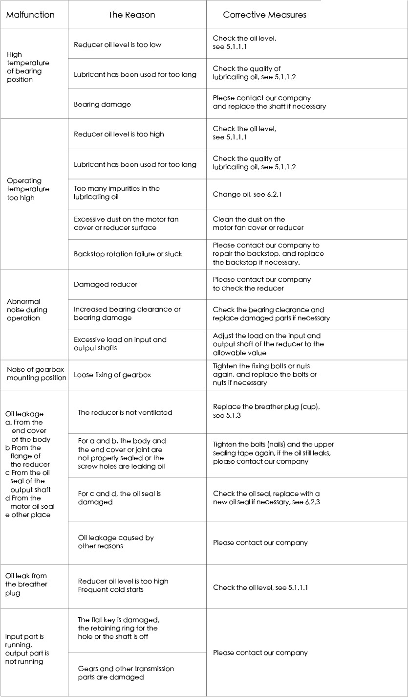
If the above three situations occur, please use the “Common Failure Causes and Corrective Measures” to determine the cause of the failure. If the cause of the failure cannot be determined for a while, or there is no suitable tool to repair, please contact our company (please check the telephone number on the reducer nameplate).
The maintenance and maintenance cycles listed in Table 2 are mainly determined according to the following working conditions:
Daily working hours:8 hours;
Work system: continuous work;
Input speed: 1500rpm;
Maximum oil temperature: 85℃ (90℃ for worm gear)
If the working conditions change, the cycle should be adjusted accordingly.
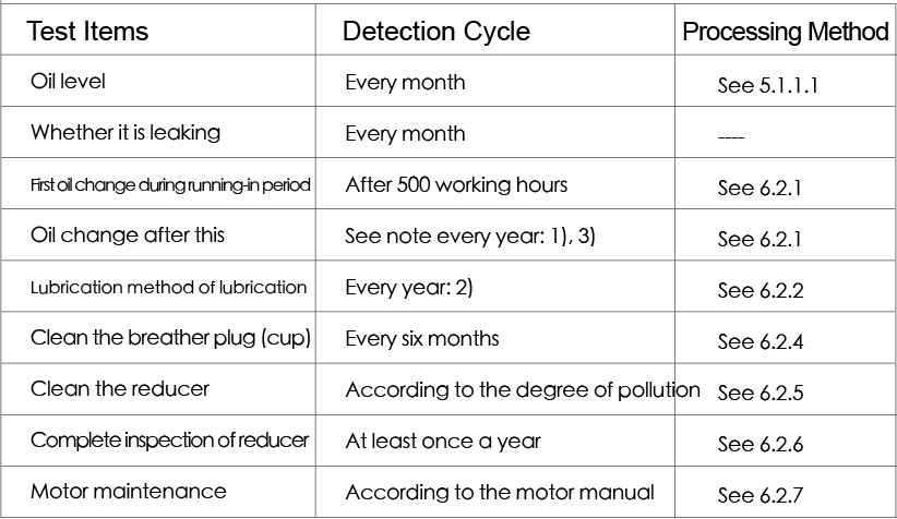
Note:
1) Using synthetic oil, the use time can be doubled;
2) The service life of the listed grease is suitable for the maximum working and ambient temperature of 85℃. The service life of grease lubrication is reduced according to the coefficient ratio of 0.7 when the temperature increases by 10 ℃;
3) For the reducer used in corrosive environment, after the first oil change during the running-in period, the lubricating oil must be checked every 2000 hours of use to avoid oil deterioration affecting the service life of reducers.
Grease lubrication of double-sealed bearings
When the double-sealed bearing leaves the factory, the bearing manufacturer injects proper amount of grease into the bearing, so it is not necessary to lubricate the reducer in the process of daily maintenance, but only need to replace it during overhaul.
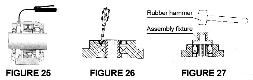
Other types of grease lubrication , except for the double seal bearing, the reducer manufactured by our company adopts the structure of straight through pressure oil filling cup, and the extreme pressure lithium base grease No.3 is used in this part when it leaves the factory.When lubricating this part, as shown in Figure 25, use a grease gun to inject the lubrication point through the oil cup.
Note! When changing grease, do not mix greases with different soap bases.
As shown in Figure 26, use a tool to remove the oil seal from the reducer. Note! In the process of removing the oil seal, the tool should not be inserted too far or too deep to avoid damage to the shaft diameter, bearing and body.
Apply grease evenly to the oil seal on the body or flange and the inner and outer edges of the oil seal.
As shown in Figure 27, use the assembly fixture to install the oil seal into the body.
Note! In the process of assembling the oil seal, if there is a sharp structure such as a keyway on the output shaft, please separate it with soft plastic
Please contact our company according to the model, factory number and date of manufacture marked on the nameplate of the reducer (please check the telephone number on the reducer’s nameplate).
Please contact our company according to the model, factory number, date of manufacture marked on the reducer’s nameplate and the structural drawing of this series of products in the operation manual (see 2) (please check the telephone number on the reducer’s nameplate).
Please contact our company according to the model, factory number and date of manufacture marked on the reducer’s nameplate (please check the telephone number on the reducer’s nameplate).
Before the reducer is stored for more than 6 months (standard storage for 6 months, calculated from the delivery date of the reducer), check whether the oil seal of the output shaft is aged and whether the lubricating oil is deteriorated.
The reducer is in a fully assembled state, and the auxiliary facilities or accessories are delivered in separate packaging. The packaging of the reducer is different according to the volume of the reducer (except for special requirements of users). The packaging is marked with “moisture-proof” and “light-proof” signs. Hoisting should strictly follow the hoisting ring on the reducer, do not use other parts for hoisting at will.
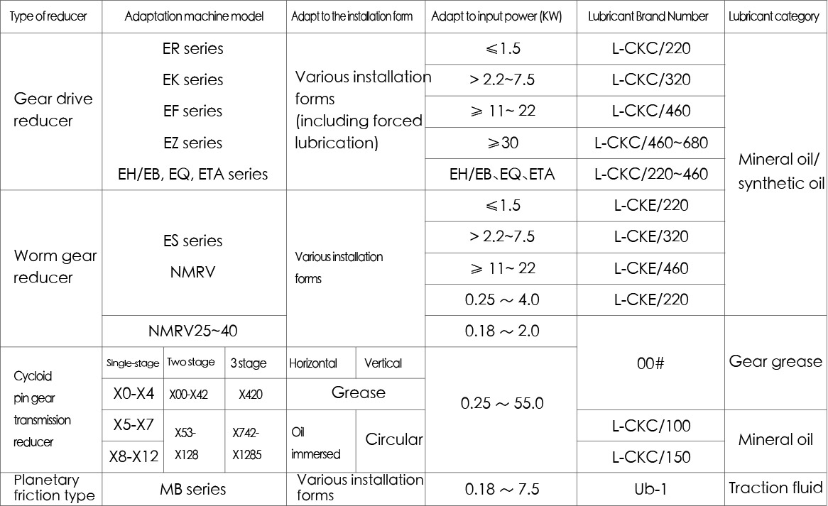
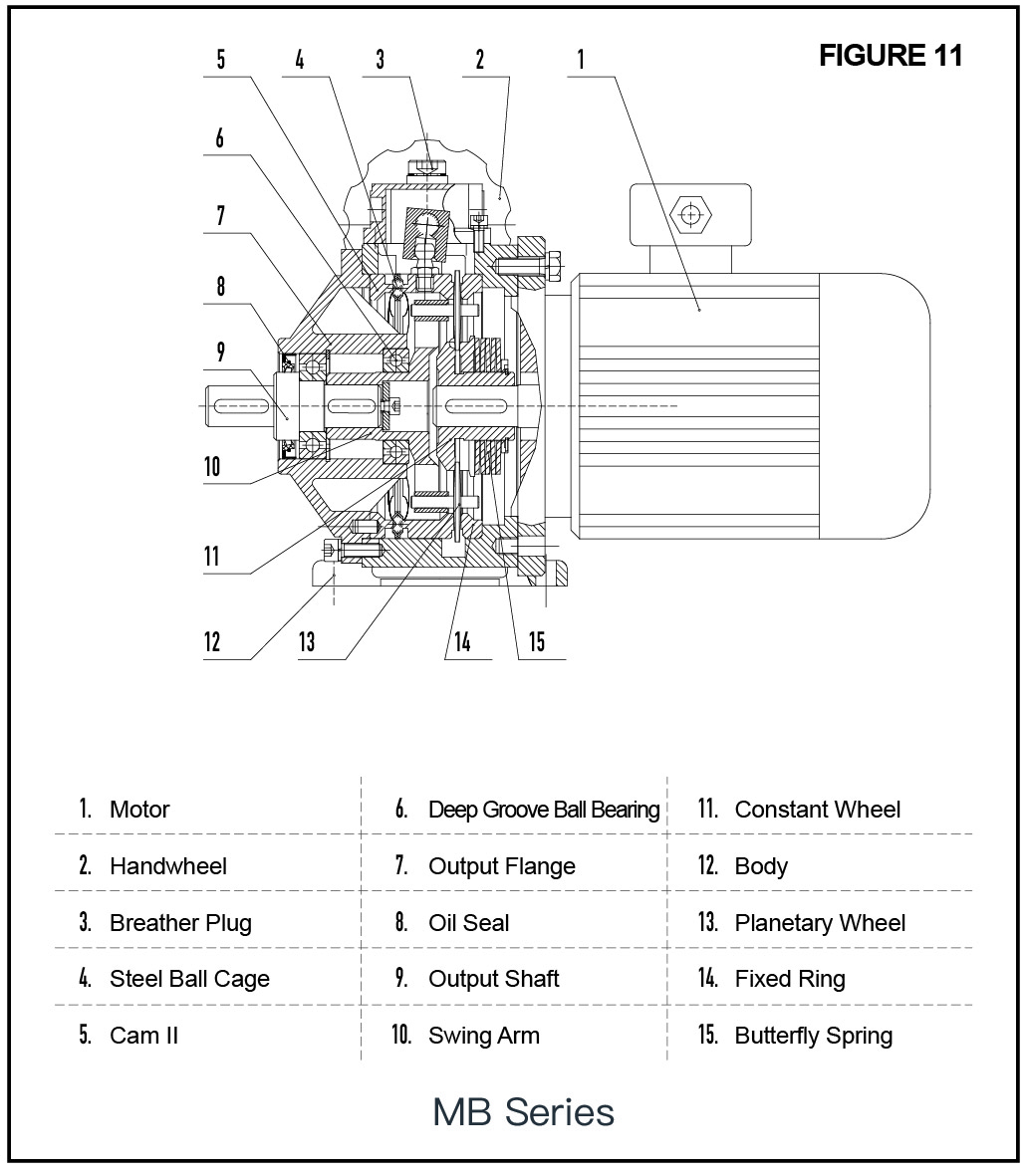
1) MB series is combined with stage gear, and the first stage gear combination part adopts grease lubrication.
2) CKC medium load industrial gear oil is suitable for the lubricating oil of low and medium speed large enclosed gear transmissions with contact stress less than 1100N/mm2.
3) CKD heavy-duty industrial gear oil is suitable for the lubricating oil of heavy-duty, high-temperature, and impact large-scale enclosed gear transmissions with contact stress less than 1100N/mm2.
4) CKE worm gear oil is suitable for copper, steel matching transmission type, bearing light load, transmission smooth without impact worm gear pair, including gear and bearing lubrication.